Overview
I've embarked on the somewhat entirely foolhardy project of fabbing a working transistor
out of silicon. One of the tools I'll need is a spincoater to spread resist on the silicon wafer.
These can be purchased on eBay for a reasonable sum. Proper spincoaters give precise speed,
automated ramp up/down profiles, exact timing and vacuum chucks to hold the wafer.
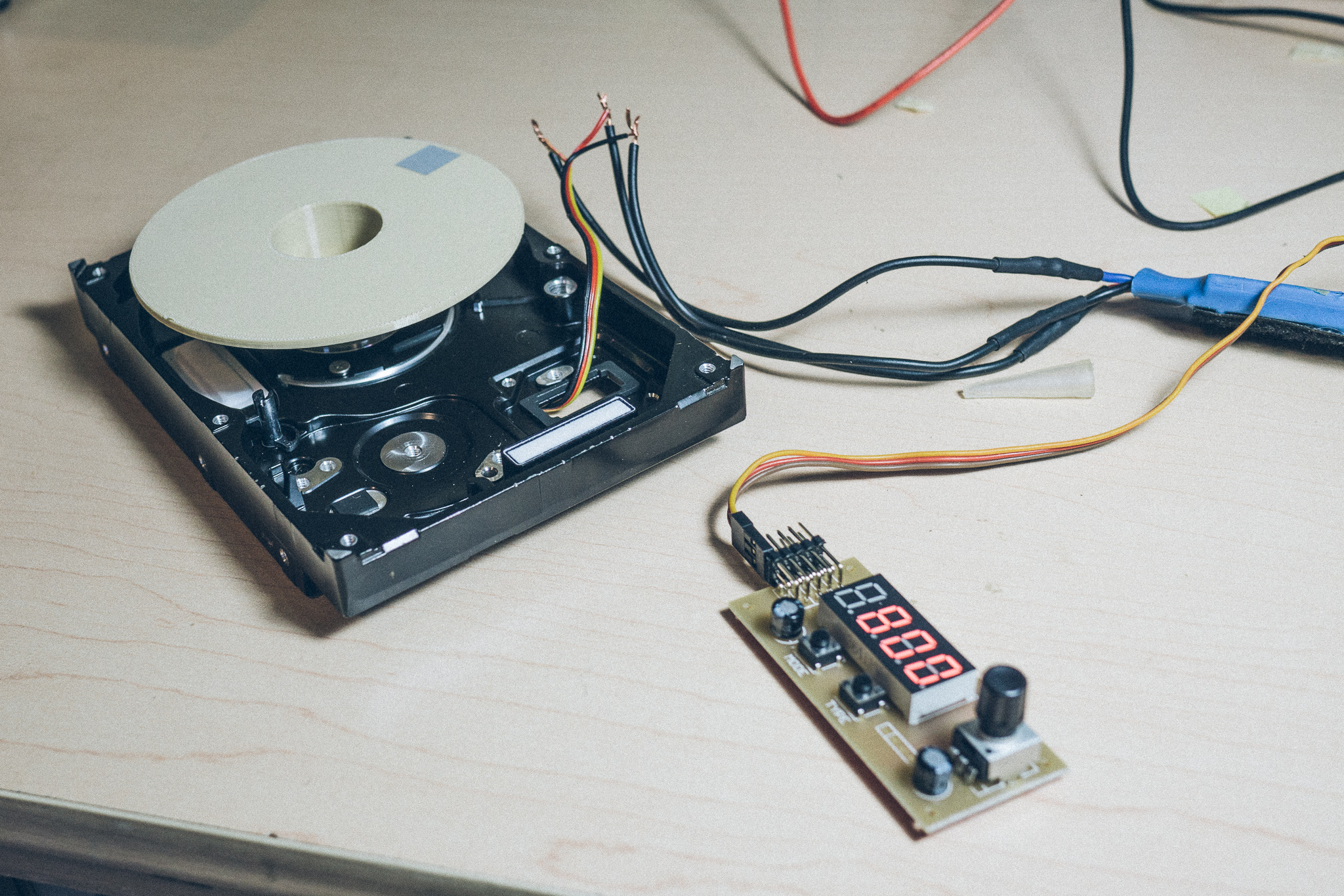
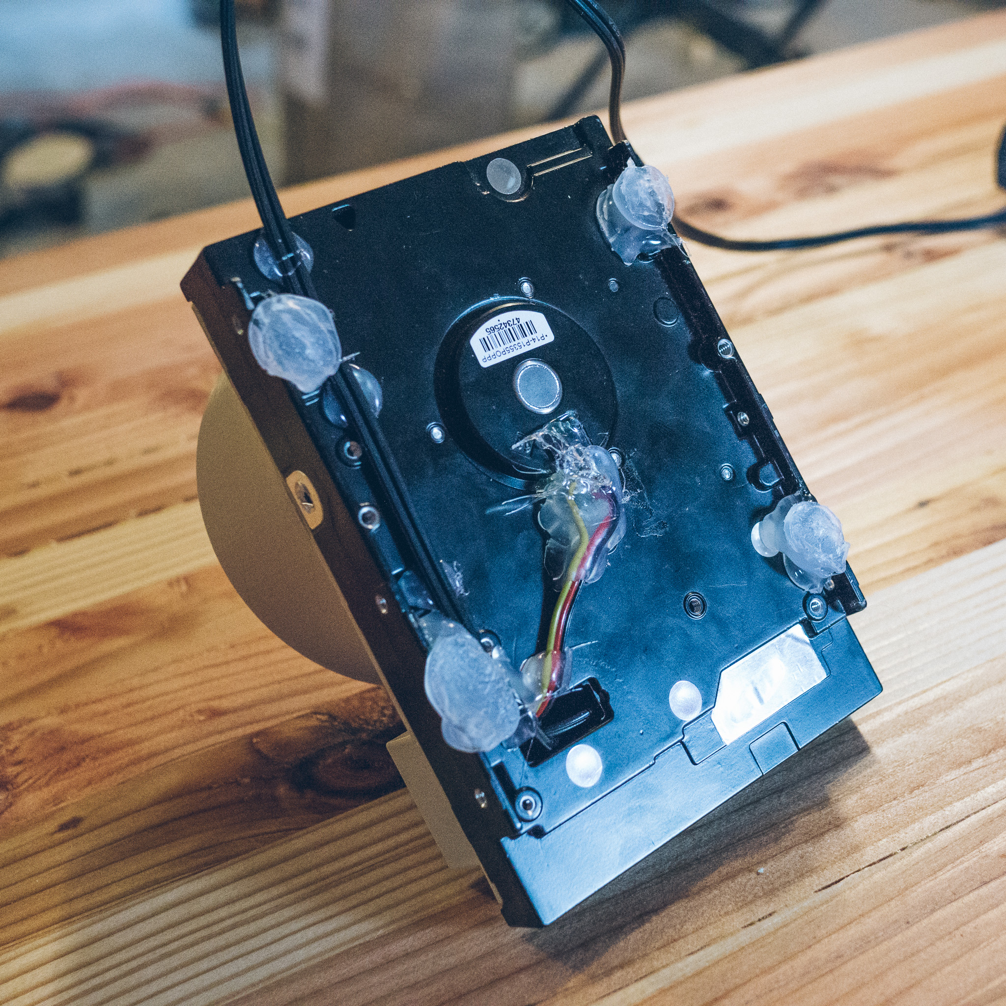
But for my purposes, DIY will probably be fine to start. I tore up an old HDD and soldered
the motor to a hobby servo controller and electronic speed control (ESC).
HDD's have brushless motors just like those used in quadcopters and FPV drones, which means
you can use a hobby ESC to drive the motor. The motor itself is tiny and has a max current draw of
400mA, so no need to buy a giant 20A ESC. I used one that I had laying around the house.
RPM of the motor can be controlled via the PWM output of a servo tester.The servo tester I grabbed off Amazon has a few extra features, such as pulse-width timing and a digital display of duty. A cheaper tester without a digital display would work fine too.
The motor takes 12V, so I rummaged in my spare parts drawer and found a small 12V 1A wall-wart which did the trick nicely
3D Printed Parts
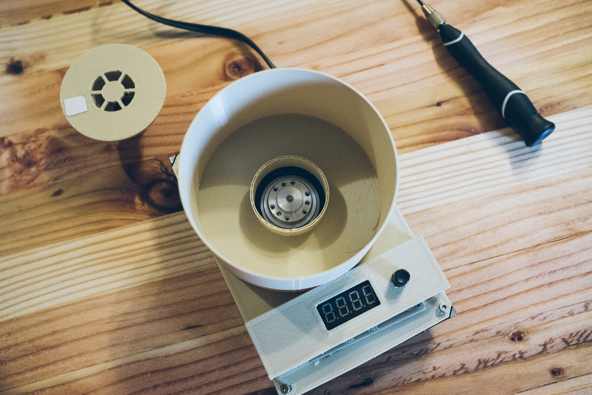
I printed a simple chuck to go on top of the motor, and mounted it with the same screws that held down the original platters. Voila, the basis of a spincoater! You can see it in action here, attempting to vibrate off the table:
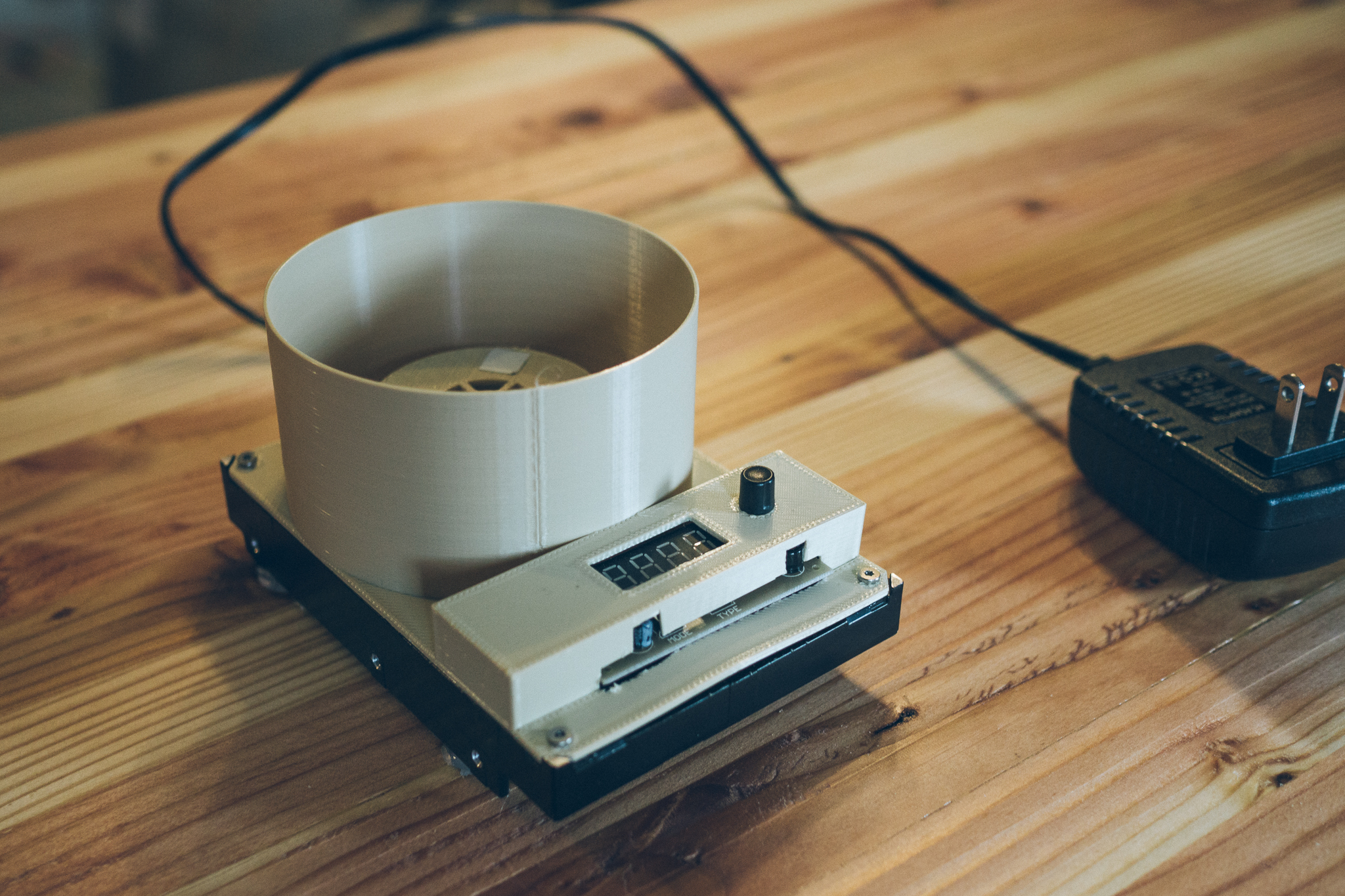
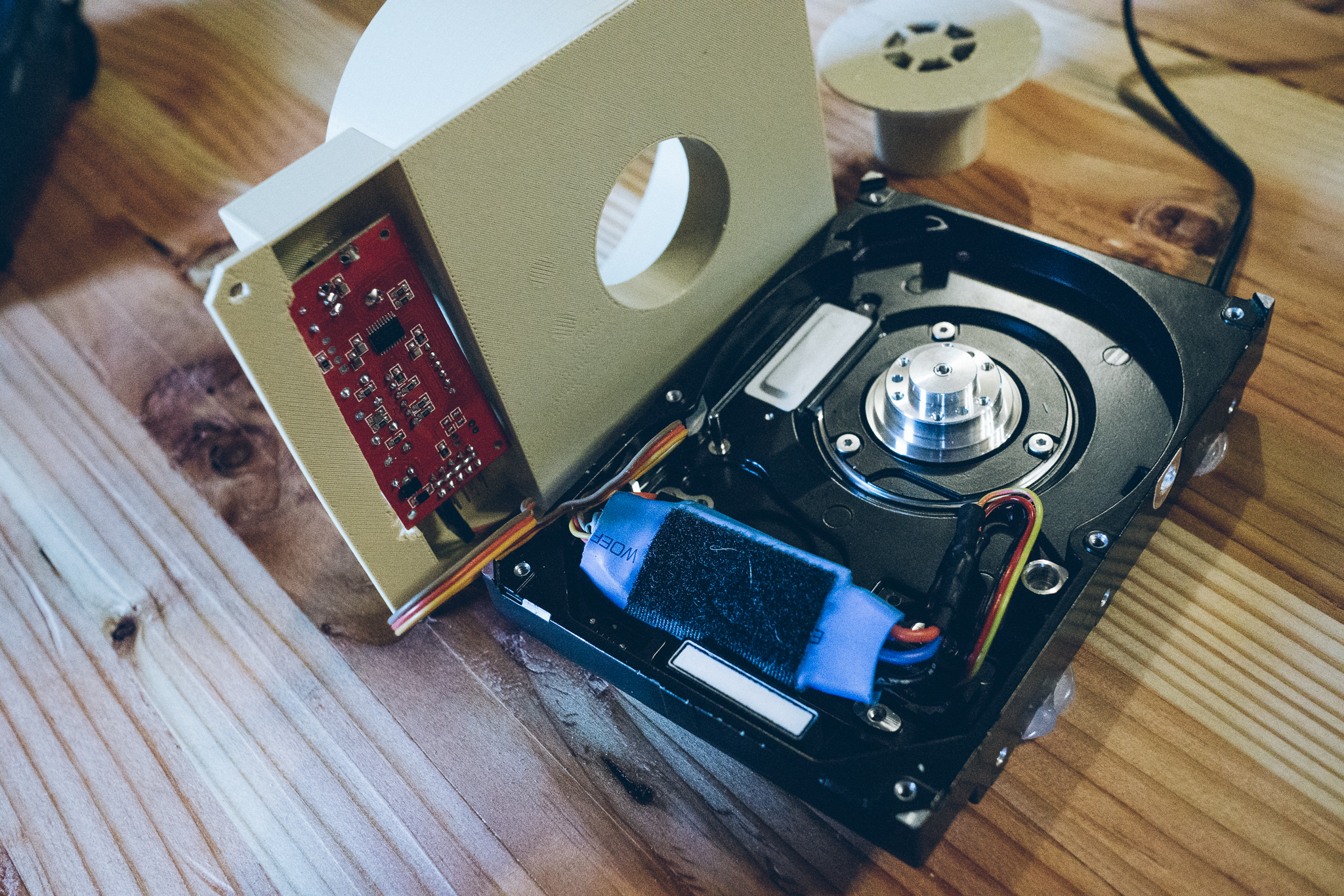
After that it was just a simple matter of printing up an enclosure to hold the electronics, and create a splash guard around the wafer chuck.

I printed several chuck designs but settled on one that is mostly hollow and relatively small. Larger chucks were more difficult for the lightweight HDD motor to get up to speed quickly, and had more momentum to slow down.
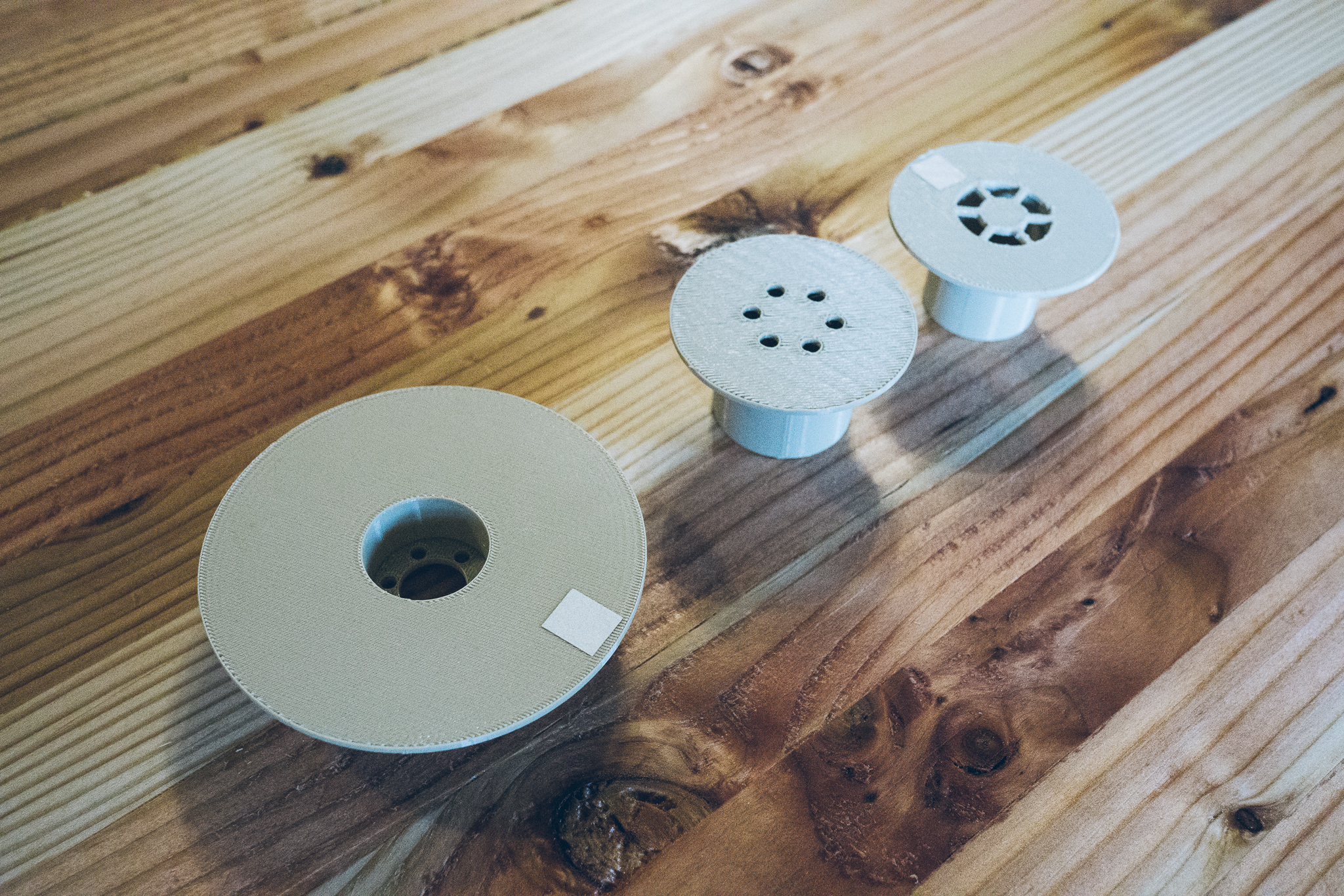
The chuck has holes aligned with the old HDD platter mounting system, so it can simply be screwed onto the drive shaft. In reality, the friction fit alone would probably suffice but I'm a bit too paranoid :)
The bottom is a disgusting mess of hot snot (hot glue). The soldered motor leads were encased in hot glue to help support them mechanically, and then some ad hoc feet were created with large blobs. That does a surprisingly good job of stabilizing the spincoater.
The electronics are just crammed inside the enclosure, nothing special in the mounting. The enclosure was essentially printed to the size of the components. Alas, I'm bad at 3D printing and measured incorrectly, so I had to cut away some of the enclosure because the edge of the board and two capacitors were too large.
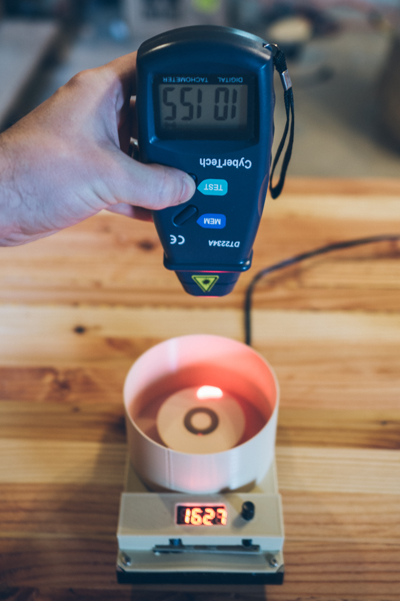
The spincoater can get up to around 10-11k RPM, based on a cheapo laser tachometer that I have. I only need speeds up to ~3000 RPM, so that will do just fine. I chose the digital display so that I can find the exact duty that gives me the RPM I desire.
And the final product in action:
Future Changes
If I ever get motivated, I'll reprint the enclosure to properly fit the electronics. More importantly, I'd like to print some kind of lid which can be used during operation. Or perhaps cut some clear acrylic so that I can see what's going on.
I'll also likely print a large knob for the servo controller… the current knob is very fiddly to position accurately.
And finally, I'll probably print some custom wafer chucks once I actually buy some wafers. My plan is to start with simply double-sided tape, but eventually I'd like the chuck to have some sort of lockdown mechanism. Unfortunately I doubt any of this janky setup would work with a vacuum system, so I'll just have to stick to hold-downs.