Tearing apart the projector, again
I've been avoiding this step, but I think it's time: I need to replace the projector's LEDs with my 405nm laser. So time to open the projector back up and start dissecting it again.
But first, some photos of the projector! I realized I hadn't posted any photos of the projector while mostly-assembled. So before I destroy it irrevocably, here are some photos of the guts.
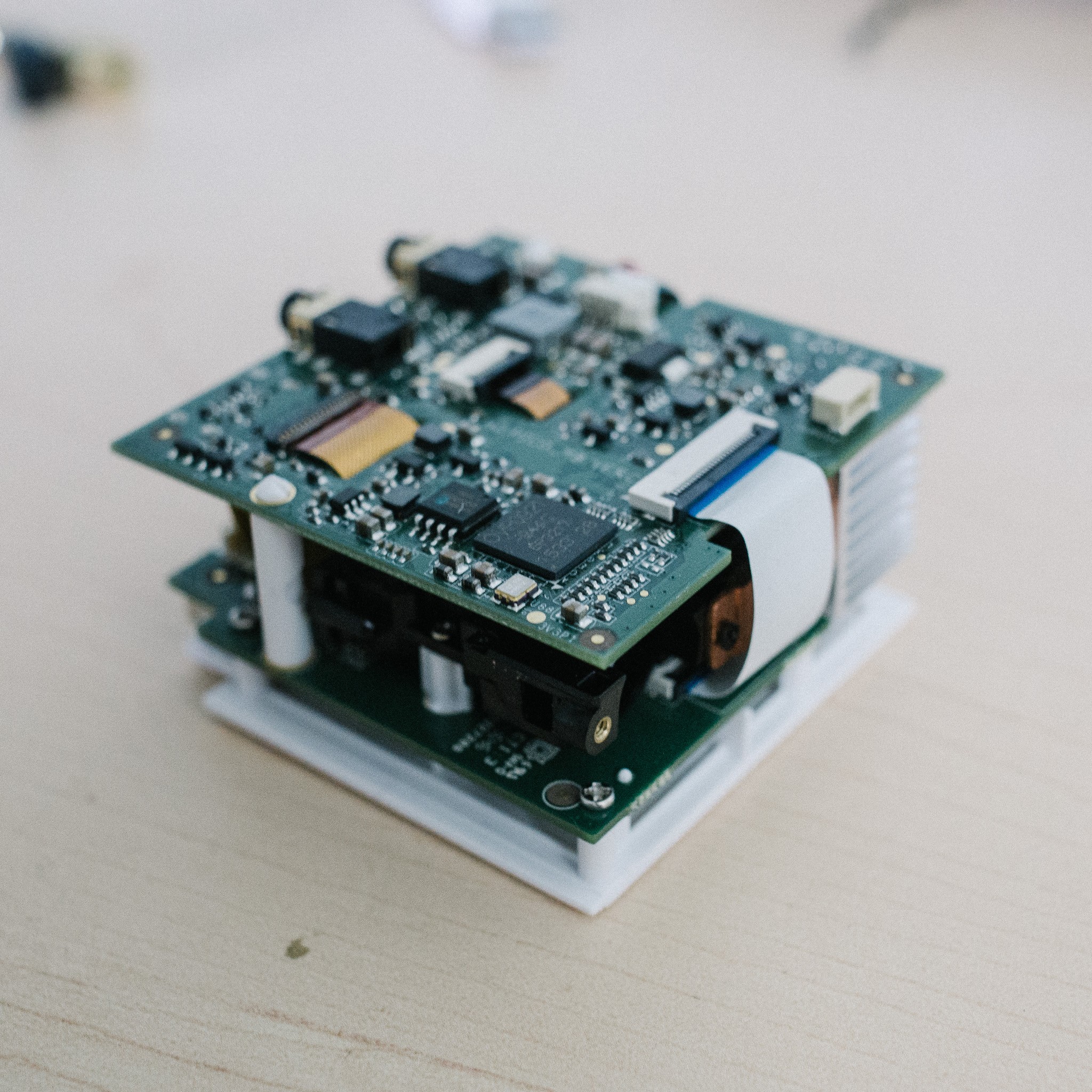
Isometric front view. The light-engine is sandwiched between two PCBs; it's the little black device peeking out from under the corner.
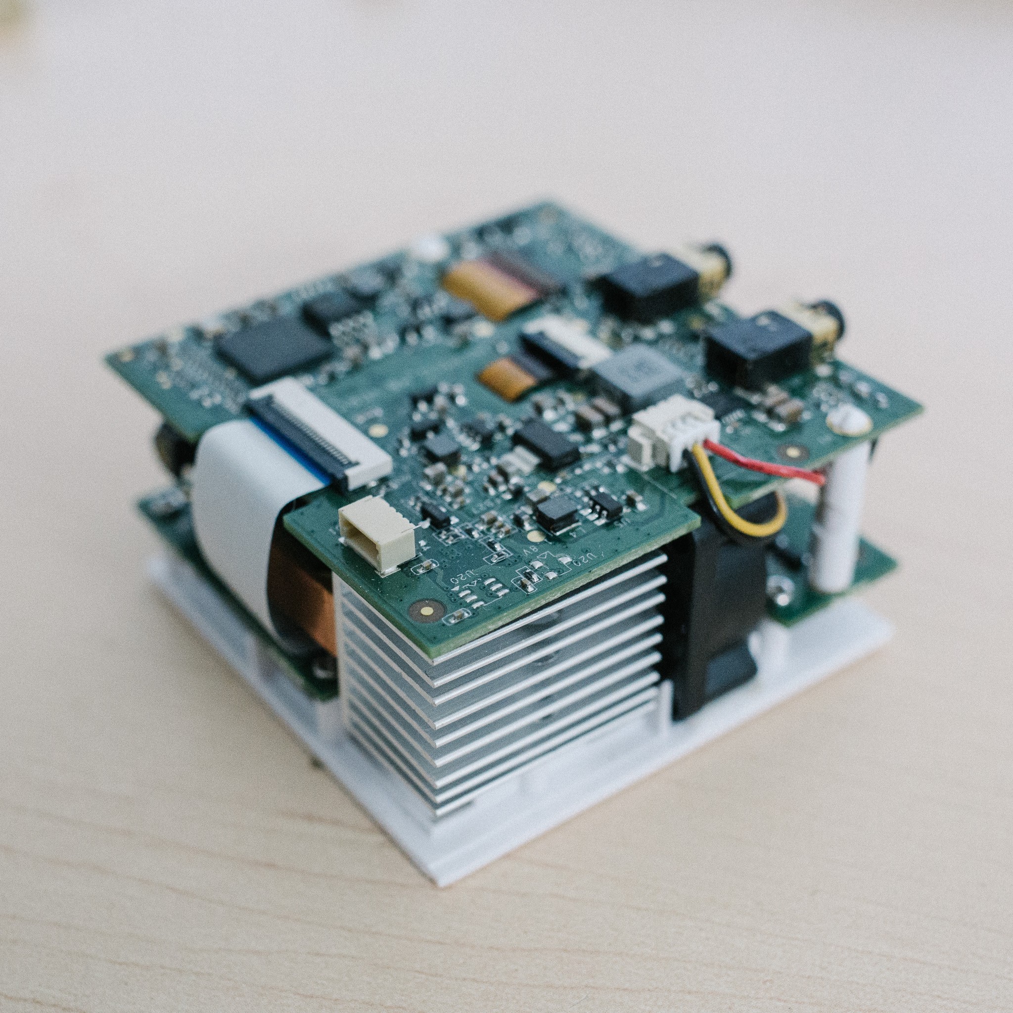
Other side. The aluminum heatsink is attached to a copper heat-spreader, which is in turn attached to the LEDs. The little black square is a tiny fan to cool the heatsink.
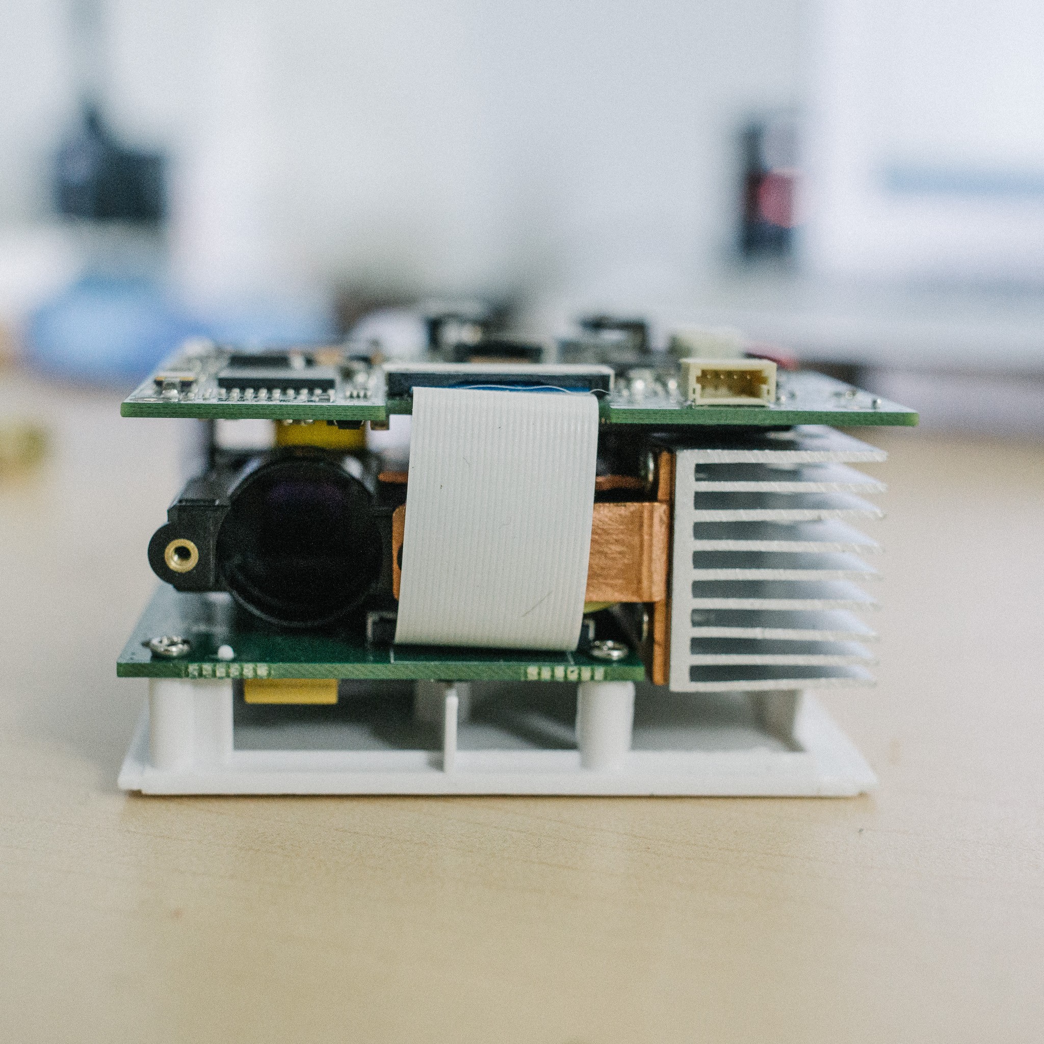
Front view, showing the projector output and heatsink. The ribbon cable connects the two boards together. All the projector logic/control appears to be on the top board, while the bottom board deals with IO (usb, HDMI, etc).
The guts, minus the top PCB. You can see the heatsink situation here a lot clearer. The wide ribbon cable controls the LCoS while the narrower cable controls the three LEDs.
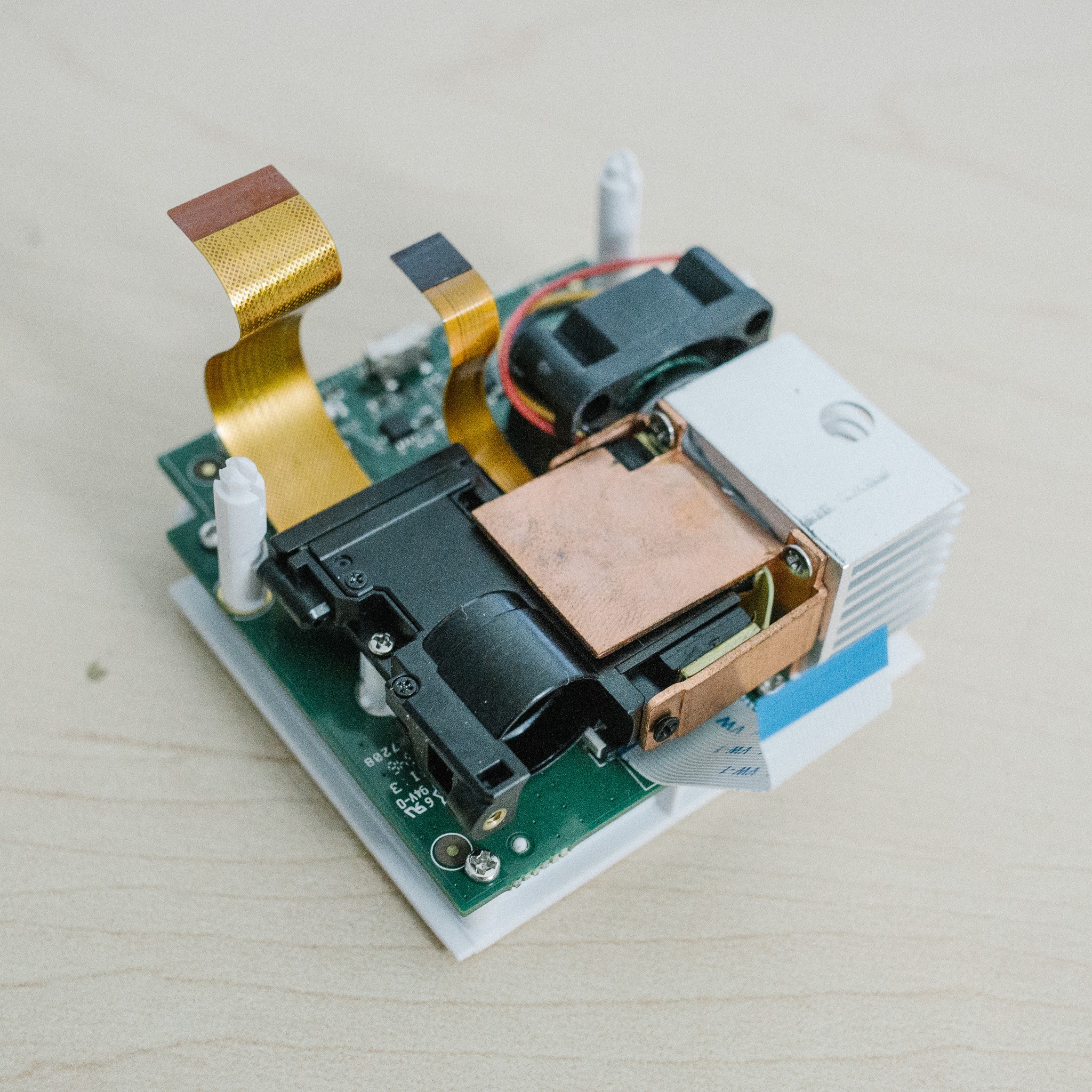
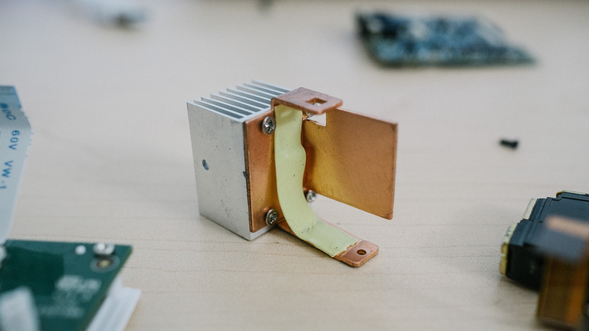
And the heatsink in isolation. The copper spreader wraps around the light-engine and makes contact with the three LEDs. A thin strip of thermal “tape” provides the heat transfer from LED to heatsink, presumably to allow a less-precise fitting and manufacturing tolerances.
Starting to destroy things
Ok, now is the part where I start to permanently remove components. I've been avoiding this because, frankly, I don't feel like buying another projector if I irreversibly ruin an important component.
But what're you going to do? The current setup isn't gonna work, so time to start disassembling :)
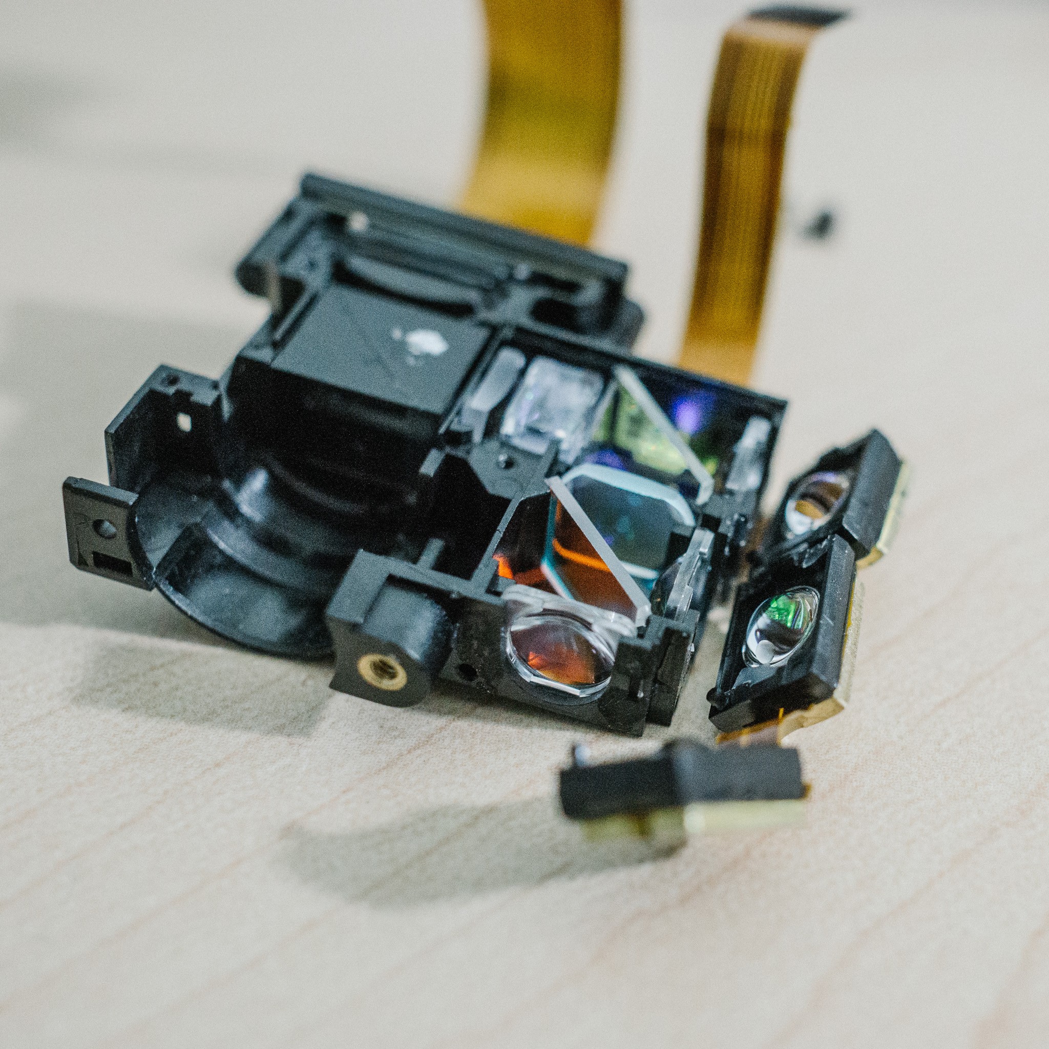
Below you can see the three LEDs which have been pried off the housing. They snap-fit into the main body and were held with a small blob of glue. Each LED has an integral lens, which projects into condenser lens on the light-engine body. A thin ribbon cable snakes between all three LEDs to provide power. And each LED has a small metal plate attached as a heatsink, which almost looks like brass?

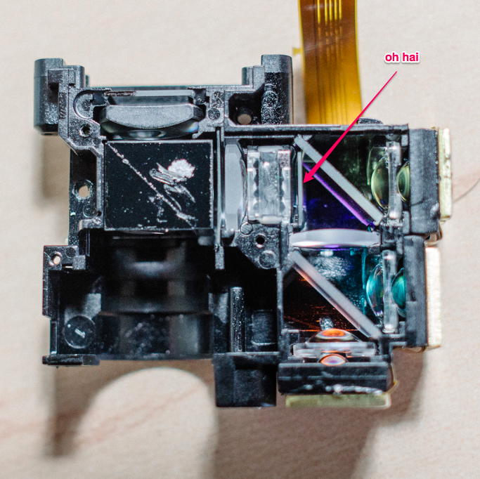
Turn your attention to those angled glass plates. I first assumed they were just simple beam-splitters, but it turns out they are dichroic mirrors. E.g. each mirror reflects a certain band of wavelengths, and transmits the rest of the light. I'm assuming this was done to clean up the spectral emission lines from each LED.
For example, maybe their Red LED put out a bit too much green light, which would muddy up the final image. The dichroic mirrors allow them to only allow “red” to pass when the red LED is illuminated, avoiding cross-contamination.
That top mirror is the “blue” mirror, and allowed bluish wavelengths to pass. When shining my 405nm (violet colored) laser through it, a small amount of blue light was projected. It appeared that the mirror was cutting some or all of the 405nm wavelength that I was interested in.
So, out it came! The mirror is super fragile, and the coating flakes very easily. I scratched the corners while trying to remove it.

Unfortunately, this didn't seem to help much. A bit more light was passing through, but still greatly attenuated.
Then I noticed this little guy:
At first I thought it might be a polarizer, but I think that's later in the optic train (right after the microlenses and PCX, before the cube beamsplitter). When studying it, I noticed that if you caught the light just right, the lens reflected a bluish color:
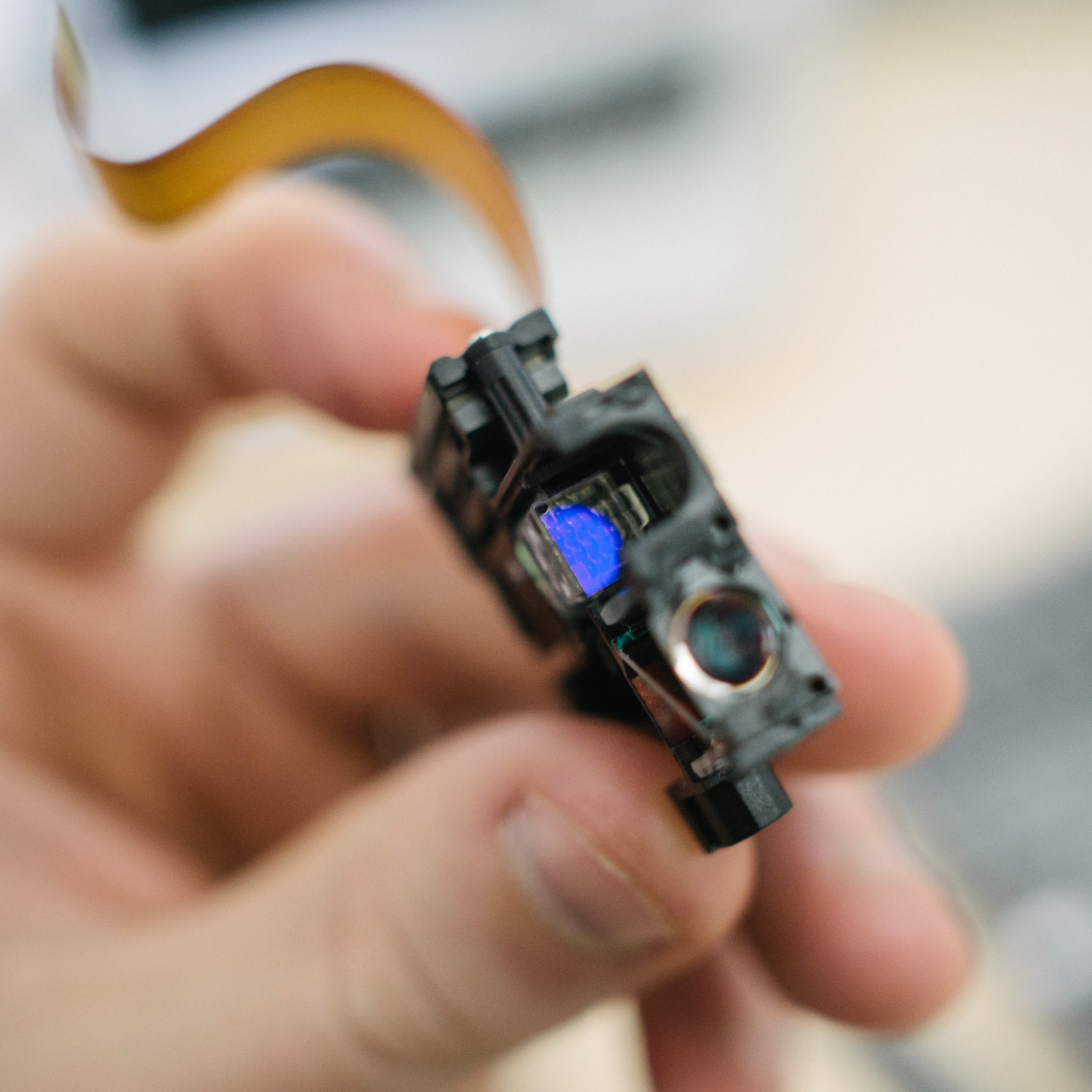
Aha! I bet that's a UV filter. Which is exactly what I don't want :)
Out that came too. Unfortunately this filter was very thin, and glued in quite well. So it broke into a bunch of pieces while being removed :(
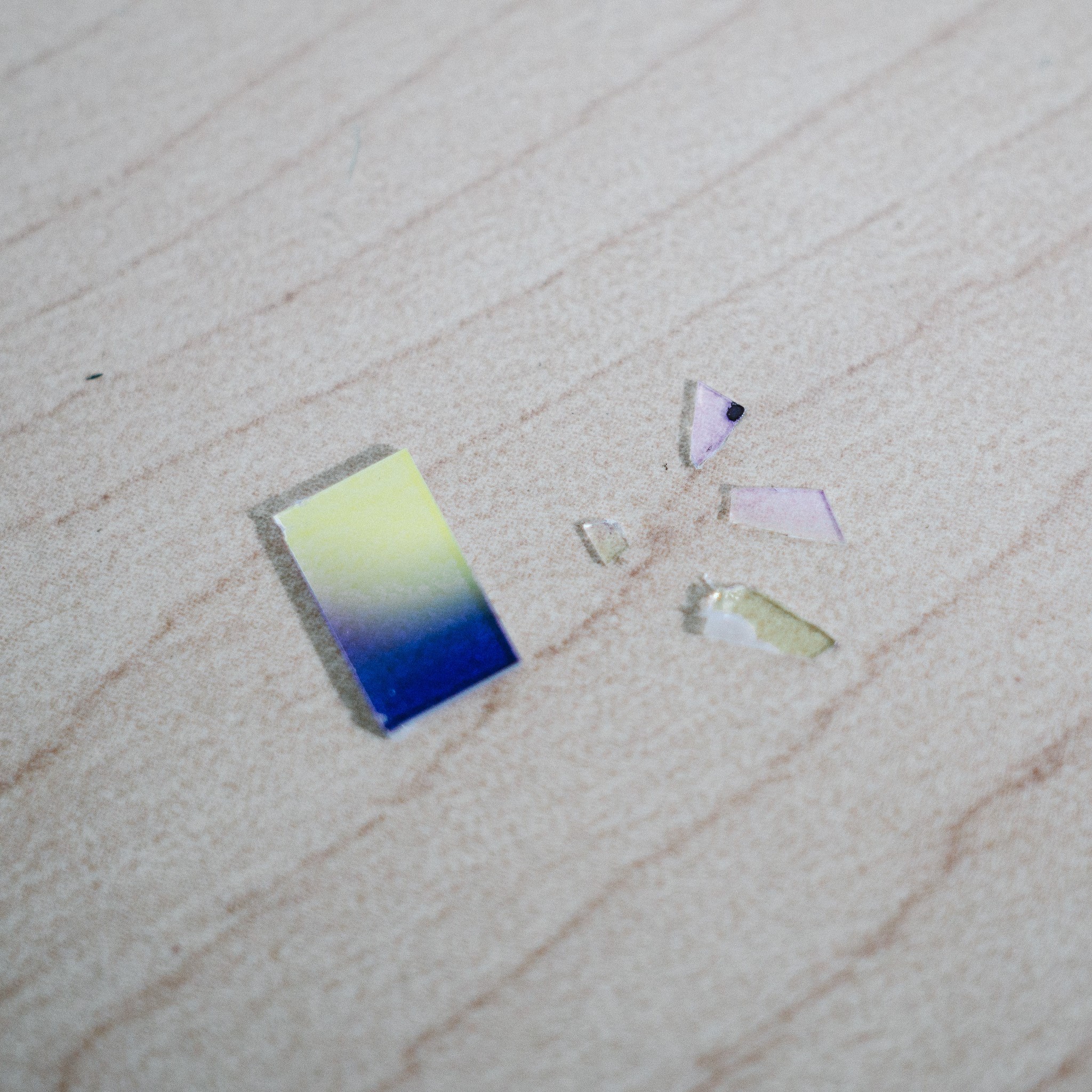
After removing that filter, my laser projects cleanly through the rest of the optical stack and doesn't appear to be attenuated anywhere in the process. Encouraging!
Moving Forward
So that's where I'm at presently. There are two directions I can pursue, still trying to decide:
- Design an enclosure to hold the light-engine body, laser, PCBs and microscope objective.
- Pull all the components out of the light-engine, design a unified body to hold all the components
The first option is appealing because many of the optics are already nicely aligned and fixed in place. I just need to design a body which aligns the rest of the external components to the existing light-engine. It has the downside of having to work around the geometry of the projector layout, which is no longer really needed.
The second option is appealing because I can streamline the optic train into a single print, remove unnecessary cruft and simplify everything (potentially removing some of those PCX lenses in the process). The downside is that I need to measure all the critical dimensions, design a much more complicated print and ensure that everything is aligned nicely.
I'm leaning towards Option #2 atm. More work up-front, but likely easier to deal with in the future. We'll see.